Speed and Revolutions
The
Development of a Slip Table for the SS Titanic
(Revised
16 October 2015)
By
Samuel Halpern
“We were working out a slip table, and we had not quite
finished when she went down. All of us were on, working out a slip table, how
many turns of the engine it would require to do so many knots; and all this,
and it tapered down.” - Titanic's 5th Officer Harold Godfrey Lowe.
Triple-Screw
Steamers Olympic and Titanic
The SS Olympic
and SS Titanic were triple-screw steamships propelled by two
reciprocating engines and a low-pressure Parsons’ turbine engine.[1]
Each reciprocating engine drove a wing propeller while the turbine engine drove
a central propeller.
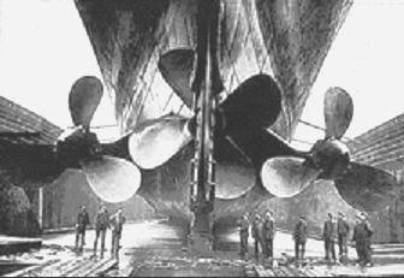
Photograph of Olympic’s Propellers
The two wing
propellers on these ships had 3 manganese bronze blades fastened to a cast
steel boss by high strength studs and nuts. This allowed for changes to the
pitch of the blades without having to replace the entire assembly. The wing
propellers had a diameter of 23 feet 6 inches, and surface area of 160 square
feet. On Olympic the original pitch of these propellers was set to 33
feet in 1911. The pitch was later
increased to 34 feet 6 inches in early 1912.
On Titanic the pitch of her wing propellers was set to 35 feet 0
inches.[2]
The central propeller
on these ships was of solid construction and cast of manganese bronze. On Olympic
the center propeller had 4 blades, and was 16 feet 6 inches in diameter with a
surface area of 120 square feet.[3] On Titanic the central propeller had
3 blades, and was 17 feet 0 inches in diameter with a surface area of 120
square feet.[4] The differences between Titanic’s
propellers compared to Olympic’s was probably done in an attempt to
reduce the power loading per disk area to improve overall efficiency.
Looking forward from a
point behind the ship as she was going ahead, the port-side wing propeller
would be rotating counter-clockwise while the central propeller and the
starboard-side wing propeller would be rotating clockwise. This can be seen
below in the animation for Olympic.
Rotation of Olympic’s Propellers Seen From Aft
Looking Forward
In summary, the
details regarding Olympic’s and Titanic’s propellers are listed
in the following table:
Engine
Orders And Speed
Three engine-order and reply telegraphs,
supplied by Messrs. J. W. Ray and Co., Liverpool, communicated engine orders
from the navigating bridge to the engine room.[5]
These telegraphs were double-faced drum instruments mounted on pedestals. Each
instrument had clear glass dials measuring 20 inches in diameter that indicated
eleven different orders. The port-side dial on each instrument indicated orders
for the port engine, and the starboard-side dial on each instrument indicated
orders for the starboard engine. Two of these telegraph instruments, the two
main engine-order telegraphs, were located on the far port and starboard sides
of the navigating bridge. They were linked to each other in such a way that
either the unit mounted on the port side, or the unit mounted on the starboard,
could be used to send orders down to the engine room to control both engines.
As they both indicated the same orders all the time, it just depended on which
of the two telegraph units happened to be more convenient to use at a given
time by the officer in charge on the bridge.
The linkage from the main engine-order
telegraphs on the bridge was connected to two 24-inch telegraph indicators down
in the engine room, one for the port engine and the other for the starboard
engine. These indicators were located about 12 feet apart on the forward
low-pressure cylinder columns of the reciprocating engines by the starting
platform. The third engine-order instrument on the bridge, the emergency
engine-order telegraph, was connected to two other engine-room indicators through
an entirely different route thereby forming an entirely separate emergency
control should the linkage from the main engine-order telegraphs be damaged.[6]
Eleven different orders for each engine could be
sent down on these telegraphs as indicated in the table below.
An engine-order telegraph built by Messrs. J. W.
Ray and Company with the arrangement used on the Olympic and Titanic can
be seen in the photograph below taken on the port side of the bridge with what
appears to be a ship's captain explaining it all to a young lad.[7]
Notice that both handles are in the forward “Stand By” position which is
telling the engineers down in the engine room to have both reciprocating
engines ready to be moved ahead shortly.

Engine Order Telegraph as Used on Olympic
Class Ships
From testimony given
by Olympic’s Chief Engineer Robert Fleming following the Hawke
incident in 1911, we are told that the turbine engine was connected up only
when they called for “Ahead Half” or “Ahead Full” on both reciprocating engines.
An order for “Ahead Half” corresponded to 50 revolutions per minute on the
reciprocating engines. The turbine engine was always bypassed when going astern
or when maneuvering engines while going ahead.
What
Do We Know About Speed, Revolutions, and Engine Orders?
From trial data of the
Olympic presented by Harland & Wolff’s naval architect Edward
Wilding at the British Inquiry into the loss of the Titanic, we know that the Olympic
made 18 knots at 60 revolutions per minute (BI 25295),
and 21½ knots at 74 revolutions per minute (BI 25292). In Duncan Haws’ book on
White Star Line ships,[8]
we get another data point for the Olympic, 22.82 knots at 79 revolutions
per minute. There was also data presented on day 16 at the British Inquiry that
75 revolutions per minute would give between 21¾ and 22 knots (BI 18372), data that was confirmed by J. Bruce
Ismay, managing director of the White Star Line. We also know from Edward
Wilding that the maximum speed expected from the Titanic with all 29
boilers connected up was about 23¼
knots (BI 25292).
The
relationship between speed and revolutions is not exactly linear. To get this
relationship we will use a non-linear equation for revolutions greater than 50
revolutions per minute (rpm), the point where the turbine engine is connected
up when going ahead:
V = K Rq
In this equation, V
is taken as the speed of the ship through the water in knots, R is the
number of revolutions per minute carried on the reciprocating engines, q
is an exponent to be determined, and K is a constant also to be
determined.
We can solve for q
by taking the ratio of Wilding’s numbers for 60 and 74 rpm in the above
equation. The result is a value of q = 0.8472. We can also use the value
of R=79 and V=22.82 from Duncan Haws to solve for K. The
result is K = 0.563.
We have therefore derived an equation
that gives us the speed of the Olympic through the water as a function
of the number of revolutions per minute carried on her reciprocating engines
with the turbine engine connected up. The mathematical relationship is:
V = 0.563 R0.8472 for R ≥
50 rpm
The machinery on the Titanic
was essentially identical to that on the Olympic except for some small
differences in their propellers as noted above. It is likely that these
difference were enough for the shipbuilders to expect a slight improvement in Titanic’s
speed over that of Olympic’s. When this question was put to J. Bruce
Ismay at the limitation of liability hearings in 1914, Ismay said “I think
about one-eighth to a quarter knot better.” If we take the ratio of the pitch
of Titanic’s wing propellers to that
of Olympic’s we get a factor of
1.0145. This results in an expected increase in speed for Titanic over Olympic of when carrying the same number
of revolutions of 1.45%.[9] The complete speed curves that are derived
for the two ships for revolutions greater than 50 rpm are shown below. (A
complete table of speeds for both vessels for revolutions greater than 50 rpm
is included in Appendix A.)

The
turbine engine ran at a rate of about 2.22 times that of the reciprocating
engines. According to Olympic’s Senior Second Engineer John Thearle, the turbine would make
between 175 and 180 rpm when the reciprocating engines were making 80 rpm, and
the maximum number of revolutions on the turbine would be about 190 rpm when
the reciprocating engines ran at their highest possible speed.[10]
The following diagram shows the relationship between the number of revolutions
on the turbine engine to the number of revolutions on the reciprocating engines
based on the above.
Ahead
Speeds Less Than 50 Revolutions
After the Hawke
collision in 1911, Captain Smith, Commander of the Olympic at that time,
was asked, “When you are working at reduced full speed, [i.e., inside coastal
waters] what do you make then?” Smith replied: “[Reduced] Full speed [is] about
20 [knots], about 75 revolutions, and Half speed 50 [revolutions] would be
about 15 [knots], Slow 30 [revolutions] would be 8 to 9 knots.” He describes
these as “easy steam, coming in and out of port.” It is very likely that he
either downplayed the speed at 75 revolutions, or more likely, was thinking
about 75 revolutions for open waters when he talked about full ahead speed.
There was evidence that Olympic’s engines were doing only 65 rpm at the
time of the Hawke collision – making perhaps 19 to 20 knots through the
water.[11]
This didn’t suit anyone who wanted to say it was Hawke that was going
too fast. It is obvious that 20 knots is about two knots too low an estimate
for 75 rpm, something which can be checked simply by referring to the data
supplied by Wilding. It is interesting that Captain Smith would have even been
thinking of 75 revolutions for reduced full speed ahead since we know that even
in coastal waters they ran much lower than that. For example, the Titanic
ran up to only 68 revolutions in her cross-channel journey from Southampton to
Cherboug, and then only 70 revolutions from Cherboug to Queenstown, and again
70 from Queenstown to Fastnet light.
So how do we
derive a table of speed Vs. revolutions when the central propeller is
disengaged? With the central turbine cut out we know we will get a reduction in
total power by about 35%.[12]
Therefore, assuming no significant added drag with the central propeller
allowed to spin freely in the slip stream, the total power is reduced to 65% of
what it is would be with all three propellers contributing. Using the
relationship that power goes approximately as the cube of the speed of the
vessel, we get:
V1 =
0.651/3 V2
= 0.866 V2
In the above, V1
is the speed of the ship with the turbine disengaged, and V2
is the speed of the ship with the turbine engaged. For revolutions under
50, the derived equation for speed thus becomes:
V = 0.488 R0.8472 for R < 50
rpm
The derived speeds for
Olympic with engine orders of Ahead
Half, Ahead Slow and Ahead Dead Slow are shown below:
The speed we
derived for the Olympic for Ahead Half at 50 rpm with the turbine engage
(15.5 knots), and the speed we just derived for Ahead Slow at 30 rpm with the
turbine disengaged (8.7 knots),[13]
are in good agreement with what Captain Smith mentioned for those speeds as
related above. The speed for Dead Slow Ahead that was derived (6.2 knots) came
about by using a value of 20 rpm with the turbine disengaged. The information
on minimum revolutions for this order came from Olympic engineer Charles
McKimm. It also seems very unlikely that the reciprocating engines would be run
at anything much less than 20 rpm which is one revolution every 3 seconds.
Making about 6 knots through the water, the ship would easily continue to make
steerageway.[14]
A plot of speed
Vs. rpm for when the turbine was disengaged is shown below. This would be
applicable for revolutions less than 50 per minute on the reciprocating
engines.
Calculating Propeller Slip and
Angle-of-Attack[15]
Propeller
Pitch is the distance that a propeller
would move in one revolution if it were moving through a soft solid medium not allowing for any slip. It is the ideal travel distance for one revolution of the
propeller.
Propeller
Slip is the difference between the ideal
travel distance and the actual travel distance in one revolution of the
propeller.
Angle-of-attack is the angle between the chord of the propeller blade and a
line representing the relative water flow across the blade.
These relationships are seen in the diagrams below. The
first diagram shows the difference between the ideal travel path of a propeller
blade and the actual travel path of the blade for one revolution. The slip is
the difference between the two paths as shown. The second diagram shows the
pitch angle of a propeller blade, the relative direction of water flow across
the blade, and the angle-of-attack between the propeller chord line and the
water flow vector.
It should be pointed out that there needs to be some
positive angle-of-attack (as shown) in order for the propeller to develop
positive thrust. If the angle-of-attack were zero, then the propeller blades
would be cutting through the water without producing any thrust. If the
angle-of-attack were negative (i.e., the water flow vector coming from above
the chord line), then a negative thrust would develop and the propeller would
tend to slow the ship down.
From the first diagram
we see that slip is nothing more than the difference between the ideal travel
distance through the water in one revolution (the propeller’s pitch) and the
actual travel distance through the water in one revolution. The percent of slip
is obtained by divided the slip by the pitch and expressing the result as a
percentage.
Mathematically,
Percent
Slip = ( 1 – actual-travel / pitch-travel ) x 100%
The percentage of
propeller slip can be calculated for a number of different speeds through the
water. To do this we make use of the diagram shown below, the known dimensions
of the propellers, and the number of propeller revolutions for a given speed
which we have derived above.
For Titanic’s
wing propellers, the pitch is 35.0 feet per revolution, the diameter is 23.5
feet, the standard 7/10 radius travel is 51.7 feet for one revolution, and the
propeller pitch angle at the 7/10 radius is 34.1°. At 75 rpm, the percent of
apparent slip calculates out to 14.6%, and the apparent angle-of-attack, a,
calculates out to 4.1°.
Deriving
A Propeller Slip Table For Titanic
We can derive the
percentage of apparent propeller slip for Titanic’s wing propellers over
a range of revolutions per minute by taking the speed through the water that we
have derived as a function of the reciprocating engine revolutions and using
the known pitch of the wing propellers. The results are shown in the table
below.
|
|
Propeller RPM |
Ship
Speed In
Knots |
Apparent
Propeller Slip (%) |
|
Turbine Disengaged |
30 |
8.83 |
14.8 |
|
35 |
10.06 |
16.8 |
|
|
40 |
11.27 |
18.5 |
|
|
45 |
12.45 |
19.9 |
|
|
50 |
13.62 |
21.2 |
|
|
|
|
|
|
|
Turbine Engaged |
50 |
15.71 |
9.1 |
|
55 |
17.03 |
10.4 |
|
|
60 |
18.33 |
11.6 |
|
|
65 |
19.62 |
12.7 |
|
|
70 |
20.89 |
13.6 |
|
|
75 |
22.15 |
14.6 |
|
|
80 |
23.39 |
15.4 |
|
|
85 |
24.62 |
16.2 |
Notice that the apparent slip for the wing
propellers jumps down significantly once the turbine engine is engaged at 50
rpm. This is because the central propeller is now carrying about 1/3 the total
thrust load of the propulsion machinery thereby reducing the loading on the
wing propellers. At the same time, the speed of the ship through the water
increases as well.
An increase in the
velocity of the water takes place in the stream of water that approaches the
disk area of a propeller because of the action of the propeller. As a point in
the stream gets closer to the propeller its velocity will start to increase
because of the lower pressure created by the movement of water through the disk
area of the propeller and will further increase as it leaves the disk area
going downstream. It is the
acceleration of that water that results in the trust produced by the propeller.
(For every action there is an equal an opposite reaction.) Under ideal
conditions, the total velocity of the water relative to the ship cannot be
greater than the pitch speed of the propeller which is attached to the ship,
our frame of reference. For Titanic making 75 rpm on her wing propellers, the
propeller pitch speed is 25.92 knots (the rotational speed [75 rpm] times the
pitch of the prop [35 ft] converted to knots). This is also known as “knots by
propeller.” The difference in speed between what the ship is actually making
through the water and what the propeller should be making based on its pitch is
what we have been calling the apparent slip speed, or in this case, 25.92 –
22.15 = 3.77 knots. This yeilds an apparent slip ratio of Sa =
3.77/25.92 = 0.146, or 14.6% for 75 rpm on Titanic.
However, the
apparent slip is not the true slip of the propellers. To get the true slip we
must take into account the velocity of the ship’s wake which reduces the
velocity of the water stream in the vicinity of a vessel’s stern. For a vessel making V knots through the
water, the velocity of the water in the vicinity of the stern is given by (1-X)
V, where X is the wake coefficient, a number that is a function of the
ship’s block coefficient, Cb, a fullness factor. For twin-screw
vessels, X = -0.2 + 0.55 Cb,[16]
and if we use that for Olympic and Titanic which had a Cb
of 0.684, we get a value for X = 0.176, or a wake velocity in the
direction of the ship’s motion of 3.9 knots when the ship is making 22.15 knots
through the water. That means that the
speed of water approaching the disk area of the propellers will actually be
18.25 knots, not 22.15 knots.
The true slip ratio
for Titanic’s wing propellers when making 75 rpm is thereby:
St (wing prop) = (1 – 18.25/25.92)*100 = 0.296, or 29.6%
For Titanic’s
central propeller, rotating at 167 rpm with a pitch of 14.5 ft, the pitch speed
is 23.84 knots. The true slip ratio
calculates out to:
St (central prop) = (1 – 18.25/23.84)*100 = 0.234, or 23.4%
The behavior of a
propeller on a vessel is not all that different from that of a fixed pitch
propeller on an airplane. The pitch of the propellers are chosen to give
highest effciency at cruise speeds. Today they have variable pitch propellers
for ocean going vessels, something not available in 1912.
Working Up Slip Tables
at Sea
As Titanic’s
Fifth Officer Lowe told Senator Smith at the American Inquiry:
As I told you, sir, we were working at our slip table, and
that is a table based upon so many revolutions of engines and so much per cent
slip; and you work that out, and that gives you so many miles per hour. This
table extended from the rate of 30 revolutions a minute to the rate of 85 and
from a percentage of 10 to 40 per cent slip; that is, minus. We were working it
all out, and of course it was not finished.

Titanic’s 5th
Officer Harold Lowe
The
revolutions per minute that officer Lowe was referring to were those of the two
reciprocating engines. However, in working out the table, the affect of the
turbine being connected up for revolutions greater than 50 rpm would show up in
the results.[17] The purpose
of working up such a table was to be able to estimate speed made good for a
number of revolutions carried. This would be used to calculate the ship’s
position using dead reckoning. Once this table was worked out it was to be kept
in the chart room.
Down
in the engine room the Chief Engineer (Bell) was required to file a report to
the Commander (Smith) every day shortly after noon that showed the estimated
quantity of coal consumed since noon the previous day, the quantity of coal
remaining, and the nautical miles run by revolutions of the engine since noon
the previous day.[18]
This distance, also referred to as “Knots by Propeller,” was obtained by taking
the average of the number of revolutions turned on both engines and multiplying
that number by the propeller pitch and converting the result into nautical
miles.[19]
On Titanic and Olympic it was the practice that the oncoming most junior officer
at the beginning of each 4-hour watch would call down to the engine room to get
the average number of revolutions per minute. The information would specify the
average rpm made on each reciprocating engine, port and starboard, during the
previous 4 hours. This was then written down by the junior officer, along with
other navigational related data, into the ship’s log book.
Based
on celestial observations, the ship’s position would be accurately ascertained
periodically. The distance run between two fixes divided by the time run
between the fixes would give the speed made good over the sea bottom. The
average number of revolutions per minute carried during that time along with
the speed made good became data points in the slip table that Fifth Officer
Lowe was talking about. The percent of slip would be obtained by taking the
actual distance run and subtracting it from the ideal distance run based on the
revolutions that were carried. This difference in distance is called the slip
distance. The ideal distance used to get that result would be calculated by
simply taking the number of revolutions that the engines turned over during the
run time, multiply that number by the pitch of the propellers (in feet), and
then converting the result to nautical miles (using 6080 feet per nautical
miles). Once the slip distance is obtained, the percentage of slip would be
given by dividing the slip distance by the ideal run distance and listing the
result as a percentage.
To illustrate what
Lowe and the other junior officers were working on, let’s take an example. It
was reported that from noon April 13 to noon April 14 the Titanic ran a
distance of 546 nautical miles. It was also reported that the order was
received down in the stokeholds on Saturday for them to be carrying 75 rpm.[20] On Sunday a bulletin was posted at 3 p.m.
down in the stokeholds stating that the they were making 77 rpm,[21]
and after 4 p.m. it was noted that they were making 76 rpm.[22]
This was all before additional boilers that were lit on Sunday morning were put
on line at 7 p.m. that night.[23]
Charles McKimm, an Olympic
engineer, had once stated, “as she gets way on, the revolutions come up all the
time, there is nothing very stationary about revolutions.” Not only did the
revolutions on these ships not remain stationary all the time, they did not
always match on both reciprocating engines. For example, it was noted that when
the Olympic was running at Full Ahead she may be carrying 80 rpm on the
port engine while the starboard engine was making only 78 rpm. A slight
imbalance between the two engine rpm values on the Titanic was also
noted by Second Officer Charles Lightoller.[24]
So in working out a
slip table it would be the average number of revolutions that is used in the
calculations. If, for the purpose of this example, the average number of
revolutions carried from noon April 13 to noon April 14 was 75.0 per minute,
then the average number of revolutions turned by the engines over 24 hours and
45 minutes, the time from local apparent noon on April 13 to local apparent
noon on April 14,[25]
would be 111,375 complete turns. Since the pitch of the wing propellers was
35.0 feet per revolution, the ideal distance traveled by the ship would have
been 3,898,125 feet, or 641 nautical miles. But the actual distance run between
noon April 13 and noon April 14 was noted as 546 nautical miles. Therefore, the
percentage of slip would be (641-546)/641×100 = 14.8%.
A slip table worked out from actual distances
traveled over ground will be influenced by the average current encountered
along the route. This is because when going against the average current set,
encountering a head current, the value of slip will work out to be somewhat
larger than the actual slip through the water. When going with the average
current set, encountering a following current, the value of slip will work out
to be somewhat less than the actual slip through the water.[26] So there may be one table used for westbound
crossings when generally traveling against the average current, and another
table that would be used on eastbound crossings when generally traveling with
the average current.
Some
Maiden Voyage Speeds And Revolutions
The table below shows some average number of
revolutions carried by the Titanic since leaving Southampton on April
10, 1912, bound for New York via Cherbourg and Queenstown up to the time of the
collision with the iceberg. These come from various sources listed. The speed
through the water shown comes from our speed table derived for revolutions
greater than 50 rpm.
As was the custom in
new White Star Line ships, the speed was slowly increased over time during the
maiden voyage. Leaving Southampton, the ship carried an average of 68
revolutions per minute which resulted in an average channel crossing rate of
just over 20 knots through the water. By late Sunday night, April 14, 1912, the
ship would have been averaging about 75-76 revolutions per minute and making a
little over 22 knots through the water, and a number of passengers noted that
the engines seemed to be were running very fast that night. And that was not quite her highest speed.
According to Bruce Ismay’s testimony at the American Inquiry:
The
full speed of the ship is 78 revolutions. She works up to 80...It was our
intention, if we had fine weather on Monday afternoon or Tuesday, to drive the
ship at full speed. That, owing to the unfortunate catastrophe, never
eventuated.
From the taffrail log
reading taken by Quartermaster George Rowe at the time of the collision, the Titanic
average 260 nautical miles through the water since noon Sunday, 14 April. This
makes for an average speed through the water of 22.29 knots. Quartermaster
Robert Hichens testified that the ship was advancing about 45 nautical miles
every two hours by log - an average of about 22.5 knots through the water - all
day that Sunday, and the quartermasters were even talking about it in their
quarters. He last recorded the log reading at 10 PM. Both of these observations are consistent with the ship carrying an average of about 75-76 rpm up
until the time of the collision at 11:40 PM 14 April. If they would have
increased the revolutions further on Monday or Tuesday to an average of 80 rpm
as Ismay hinted they were going to do, then an average speed through the water
of about 23¼ knots might have been seen. And if they would press the engines to
go up to 83 rpm, a maximum number that we have from Olympic’s Chief
Engineer Robert Fleming, a speed of about 24 knots through the water would have
likely resulted. Unfortunately, they never got the chance to really find out.
Acknowledgements
I would like to thank
Mark Chirnside for sharing with me detailed information from several of Olympic’s
engineers, and access to several pages of the engine logs of the Aquitania
that showed the various items recorded. Also thanks to Rebecca Lawrence for the
picture of the engine-order telegraph taken on the bridge of a White Star Line
vessel. In addition, I’d like to thank Captain Charles Weeks of the
Maine Maritime Academy for his enlightening explanation of how slip is
calculated for a ship at sea.
APPENDIX A
The following are the
complete speed tables derived for Olympic
and Titanic for revolutions on the
reciprocation engines from 50 rpm to 85 rpm with the turbine engaged. The
revolutions on the turbine engine would be 2.22 times that of the reciprocating engines.
|
Revolutions Per
Minute |
Speed
(knots) |
|
|
Olympic |
Titanic |
|
|
50 |
15.48 |
15.71 |
|
51 |
15.75 |
15.97 |
|
52 |
16.01 |
16.24 |
|
53 |
16.27 |
16.50 |
|
54 |
16.53 |
16.77 |
|
55 |
16.79 |
17.03 |
|
56 |
17.04 |
17.29 |
|
57 |
17.30 |
17.55 |
|
58 |
17.56 |
17.81 |
|
59 |
17.81 |
18.07 |
|
60 |
18.07 |
18.33 |
|
61 |
18.32 |
18.59 |
|
62 |
18.58 |
18.85 |
|
63 |
18.83 |
19.11 |
|
64 |
19.09 |
19.36 |
|
65 |
19.34 |
19.62 |
|
66 |
19.59 |
19.87 |
|
67 |
19.84 |
20.13 |
|
68 |
20.09 |
20.38 |
|
69 |
20.34 |
20.64 |
|
70 |
20.59 |
20.89 |
|
71 |
20.84 |
21.14 |
|
72 |
21.09 |
21.39 |
|
73 |
21.34 |
21.65 |
|
74 |
21.58 |
21.90 |
|
75 |
21.83 |
22.15 |
|
76 |
22.08 |
22.40 |
|
77 |
22.32 |
22.65 |
|
78 |
22.57 |
22.90 |
|
79 |
22.81 |
23.14 |
|
80 |
23.06 |
23.39 |
|
81 |
23.30 |
23.64 |
|
82 |
23.54 |
23.89 |
|
83 |
23.79 |
24.13 |
|
84 |
24.03 |
24.38 |
|
85 |
24.27 |
24.62 |